SSST Blog 5/6/20
Progress for the week:
This week the SSST completed the Final Presentation that listed and explained the final design, analysis, and conclusions of each sub-team. Beforehand, many of the objectives that were set forth at the beginning of the year were completed this week. In the following sections, the overall progress for the guideway, bogie, and controls team will be mentioned.
Guideway Team
The team was able to render a solid model of the overall completed track using Fusion 360. The model was imported from Solidworks to Fusion 360, where each part was assigned a material to render. Figure 1 shows an example of the overall guideway, with the pod and bogie hanging on it.

Figure 1. Render of fully assembled guideway, pod, and bogie.

Figure 2. Render of fully assembled guideway, pod, and bogie.
The presentation included the final design intent for the project, such as how the team would have built the track using a layer caked design as shown in Figure 3. A motion simulation of the track was also produced using Solidworks, showing two bogies/pods traversing around the track.

Figure 3. Top and bottom layers of a straight that are layered over one another.
The y-junction and y-switch rail for the guideway was also completed this week. The guideway team decided it was best to 3D print the third rail so that it could be manufactured in one go. This included supports to which the third rail would hang on, and that support itself would connect to the rods coming from different sides of the track, as seen in Figure 2.

Figure 2. Render of fully assembled guideway, pod, and bogie.
The presentation included the final design intent for the project, such as how the team would have built the track using a layer caked design as shown in Figure 3. A motion simulation of the track was also produced using Solidworks, showing two bogies/pods traversing around the track.
Figure 3. Top and bottom layers of a straight that are layered over one another.
Finite element analysis (FEA) was also simulated using ANSYS and Solidworks. Based on the results, the team decided that the simulation's results were negligible, as total deformation proved to be less than 0.003 inches.
Controls Team
The controls team was able to design two separate apps. One allowed data to be transferred to the BLE and work with the Arduino code. The other was a user interface system app that allowed users to experience what it might be like to use the SPARTAN Superway. A Fritzing diagram was also created to show future students how the components are connected, as seen in Figure 3.

Figure 4. Fritzing diagram of the overall controls
The barcodes for the stations were also presented, showing that the Arduino code would have feedback from the sensors on the Pixycam. A flow chart of the code was created by Asmaa to explain how the BLE would work, as seen in Figure 5.

Figure 5. Flowchart of the Arduino code.
The app created by Julio was also explained, as seen in the video below:
Bogie Team
The bogie's final design included a functional swiveling mechanism, gear ratio, and y-switch used for the pods as seen in Figures 6, 7, 8.
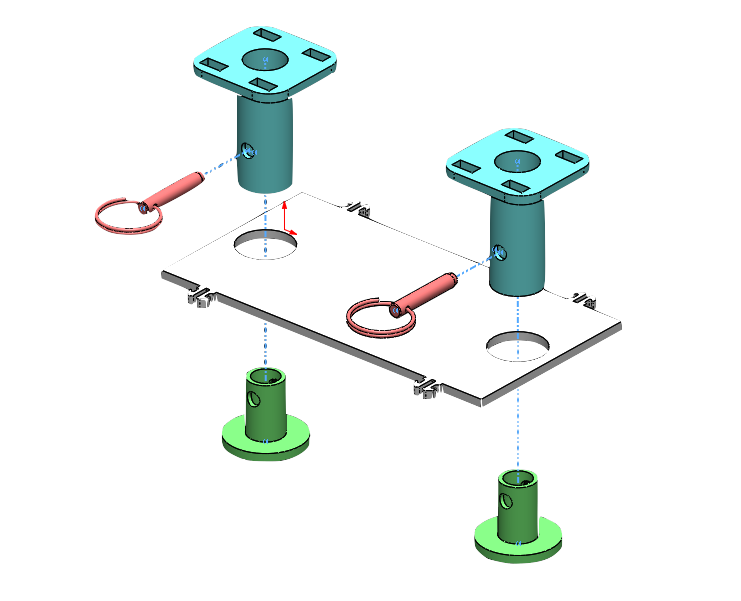
Figure 6. Swiveling mechanism used for the pods
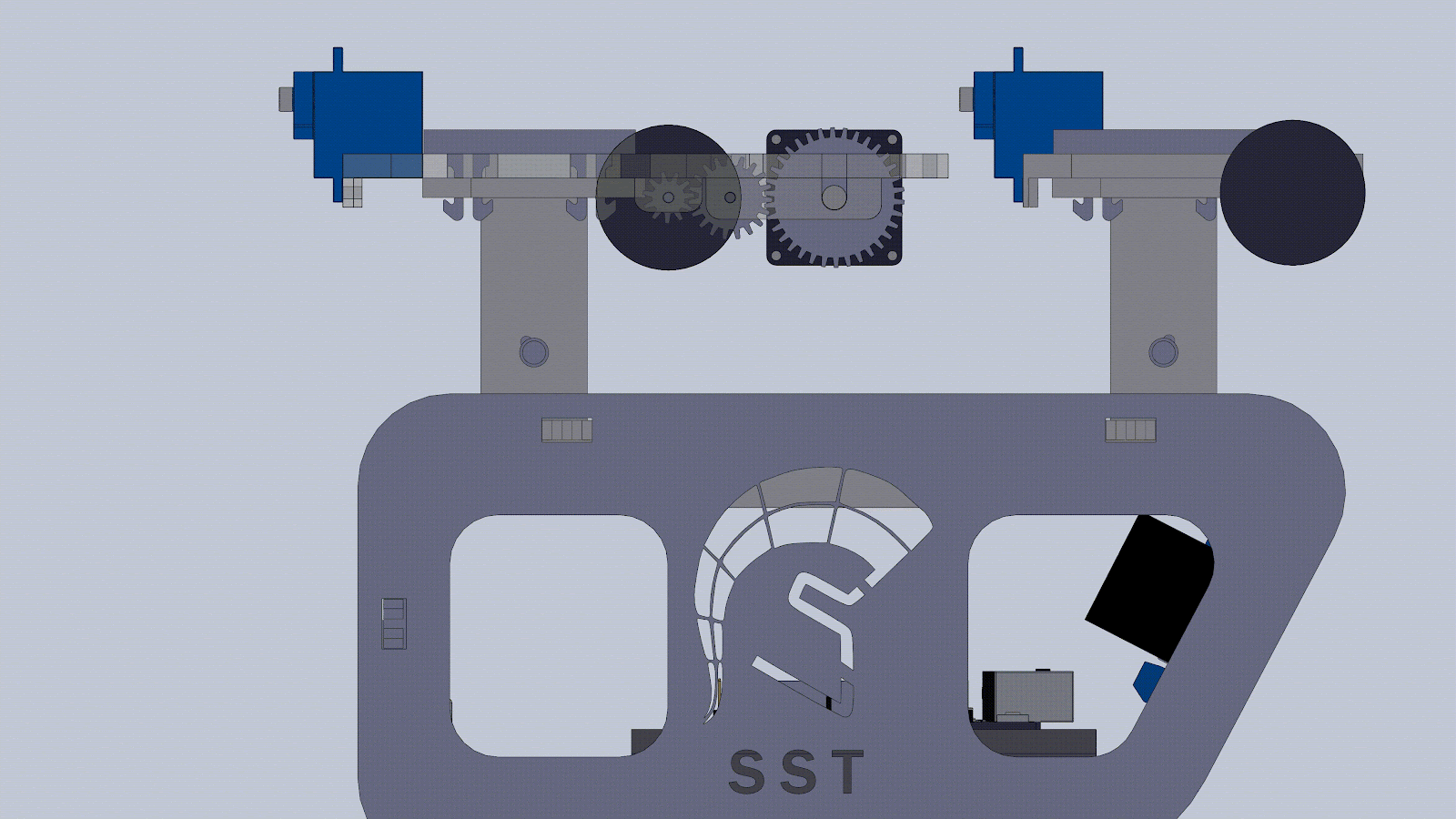
Figure 7. Gears used for the bogie.

Figure 8. Y-switch used for traversing the y-switch rail.
The snap-fit design of the pod allows students to open and close the object to fit parts into it, as shown in Figure 9.

Figure 9. 3D printed pod design
Overall, the team was able to complete the main objectives that were tasked at the beginning of the semester. The guideway team was able to design a functional and interchangeable track with a working y-junction. The bogie team successfully designed a swiveling mechanism that allowed smooth movement throughout turns. And both the guideway and bogie team created a y-junction and y-switch that prevented the bogie from falling between gaps in the track. The controls team was able to successfully design an anti-collision system and complete an Arduino control system that connects to a user-friendly iOS app.
The team will be creating a Final Report that will have future suggestions for students to come.
Written by:
Justin Ghieuw
May 6th, 2020
Comments
Post a Comment