SSST Blog 4/8/20
Progress for the week:
Controls Team
One of the most anticipated moments in the iOS app developing journey was completed. This was to succesfully establish a connection to the BLE via the a custom-developed app. The issue that the team was having was that the UUID that was input into the code, was not the correct identifier. So essentially the code would be searching forever for a UUID that was not connectable. Once the team discovered the correct UUID, the connection was a breeze. The output screen of the succesfull connection can be seen below in Figure 1:
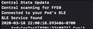
Figure 1. Output screen of iOS app on Xcode.
Now that the app is connected to the BLE, the next step is to gain inspiration from the HM10 Serial app that the team has been using to test the components. In their app, once connected, the keyboard is used to send ASCII characters to the BLE and those values correspond to different stations on the guideway, these stations are different numbers and are set up in the master Arduino code. The team hopes to implement a similar version of that keyboard interface into the Small Scale app. It seems a bit daunting and in case the keyboard is not succesfully functional, there are other UI elements that can be used to replace the keyboard, such as a slider, button or switch. As the team tests, a decision will be made as to what is the best next step moving forward. Regardless, having established that connection between the app and the BLE, is an accomplishment to be proud of. The first step of the keyboard being implemented into the Small-Scale app can be seen below in Figure 2:
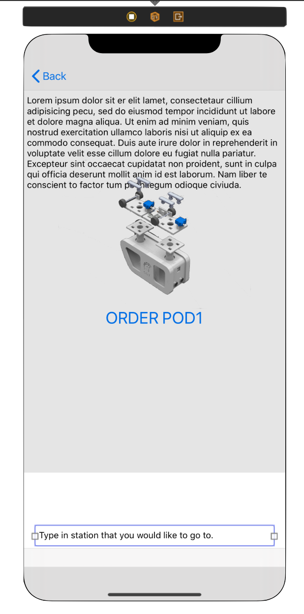
Figure 2. Implementation of keyboard into iOS app.
In adition to progress made on the app, the master Arduino code was completed by Asmaa and the flow chart of this can be seen below in Figure 3:

Figure 3: Flow chart of master Arduino code,
The layout of the electronic components was also updated using Fritzing, it can be seen below in Figure 4:
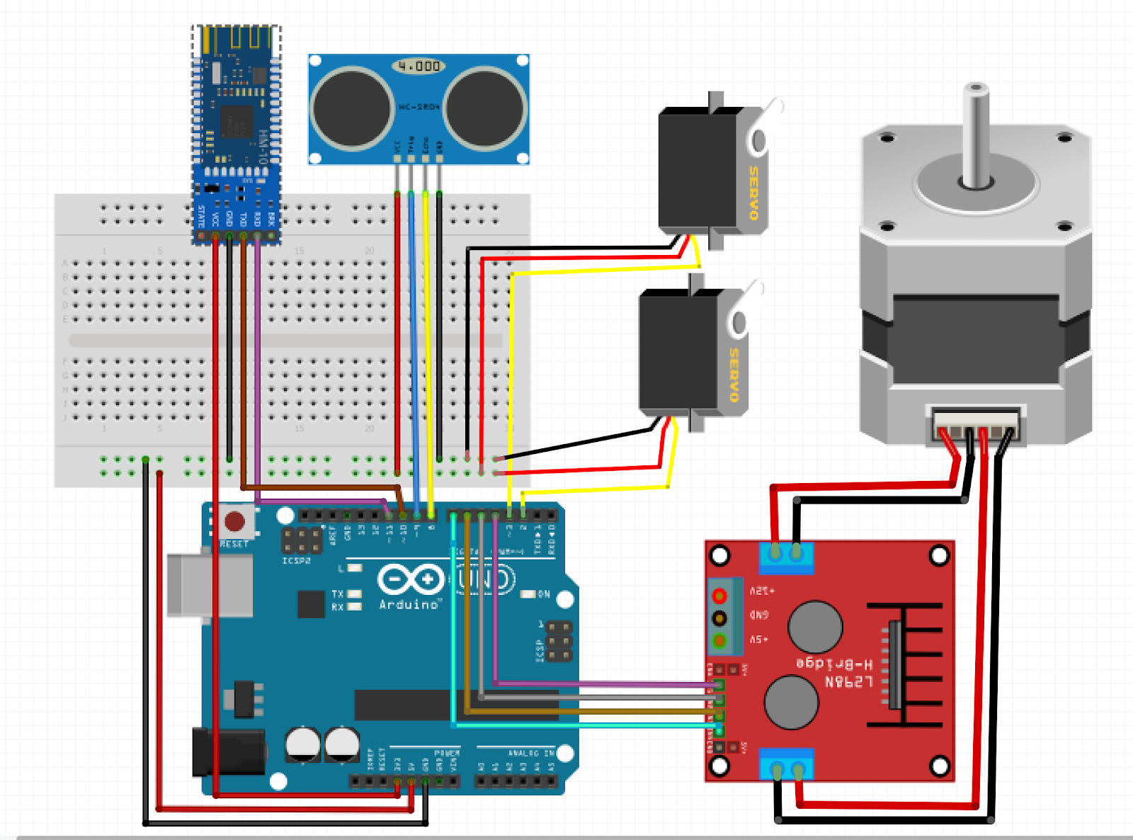
Figure 4. Frizting layout of all the electronic components.
The next section will discuss the progress made by the guideway team.
The guidway team had begun to assemble the pieces of the guideway and were making good progress. Unfortunately due to the shelter in place order, assembling the guideway had to be halted and it is unknown as to when assembling will be able to resume. It is looking good overall and the team is happy with the rigidity of the guideway.

Figure 7. Outerloop of guideway assembled before shelter in place order.
The team also made further progress on the y-switch of the guideway. This part of the guideway was practically ready for fabrication until the lockdown occurred. The updated y-switch can be seen below in Figure 8.

Figure 8. Updated y-swtich in Solidworks.
There was some interference that was detected between the right side of the y-switching mechanism and the y-switch. This interference can be seen below in Figure 9:
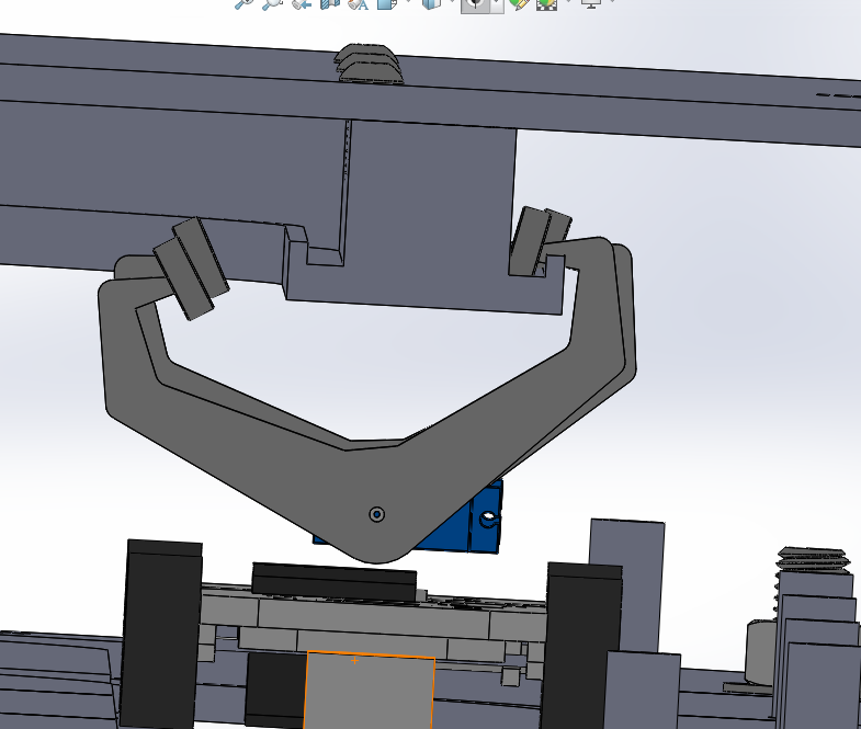
Figure 9. Interference detected between the right side of the switching mechanism and the y-switch.
In the first presentation, it was pointed out that the 1 m/s spec for the bogie on the guideway was way too fast. The bogie team agreed with Dr. Furman and Ron and reduced the spec to be .2 m/s. The assembly of the switching mechanism on the bogie is almost complete and will use bearing and a shoulder screw to secure it in place. This can be seen below in Figure 10:

Figure 10. Bearing and shoulder screw on the switching mechanism.
Progress was also made on the bogie itself by adding the slots where the gears that were purchased would go on the actual bogie. In the meantime it will be modeled in Solidworks as shown below in Figure 11:
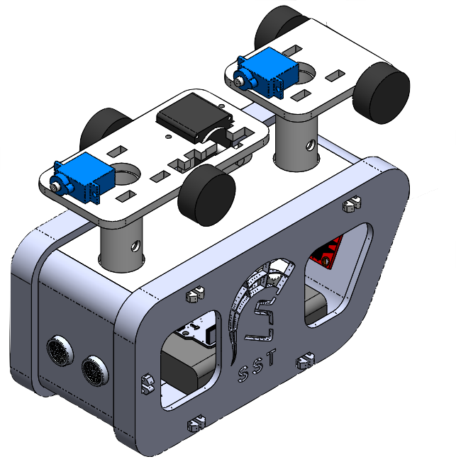
Figure 11. Slots added to bogie design in Solidworks to account for gears.
Some nice renders were also created using Fusion 360 to get a better idea as to how the pod would have looked once fully assembled. In Figure 12 shown below, a side view of the pod can be seen with a transparent material to depict how all of the electronic components would fit inside the pod.

Figure 12. Side view of the pod rendered in a clear material.
The pod was also rendered in PLA to show how the pod would have looked like if the new versions were to have been printed. This can be seen below in Figure 13:

Figure 13. First iteration of pod with snap-fit design.
The location of the Pixy2 was also switched to the bottom of the pod so that as it is traversing across the guideway, the Pixy2 can scan the barcodes that will be placed strategically on the rods of the guideway with a custom 3D printed adapter. The new location of the Pixy 2 can be seen on the right bottom side of the pod as show below in Figure 14:

Figure 14. First iteration of pod with snap-fit design.
The next sections will discuss the progresss made as a whole and the future plans for the coming weeks.
The main progress made this week as a whole was preparing for the second presentation of the semester. Due to the shelter in place, the presentation had to be via Zoom which was actually a bit more challenging than expected. Since this was the first presentation that a lot of the team members had ever done via Zoom, it was interesting to notice the difference that it makes versus presenting in person. Not that many people had their cameras on, so the majority of the time, it felt like we were talking to ourselves, and were not getting the live feedback that we are used to. Furthermore, it was a bit challenging to keep a smooth flow from slide to slide because only one person had control of the slides and there was a lag from time to time. Regardless, the team was happy with the presentation as a whole given that it was an abrupt change in the medium we were presenting through.
After the presentation, the team plans to continue making progress towards the ending of the semester. Since physical manufacturing has halted, the remainder of the analysis for the guideway, pod, and bogie will all have to be done via Solidworks and ANSYS. Luckily for the controls team, two separate team members have the components to continue testing the iOS app and the electronic system. Presented with this unusual challenge of having to do everything remotely, the Small-Scale team is hopeful that good progress can still be made toward the overall goals.
Written by:
Julio de Pereda Banda
April 8th, 2020
Comments
Post a Comment