SST Blog 10/23/19
Progress for the week:
Controls Team
This week consisted of presenting the progress on the iOS app as well as the motor and ultrasonic sensors for the Arduino. The iOS app currently has three main tabs: a home, order pod, and map tab as seen in Figure 1.
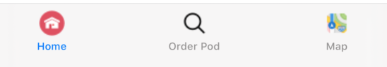 |
| Figure 1. Main tabs of iOS app. |
There are small parts of code included (Figure 2), but there needs to be more practice done to meet the requirements for the app. All of the code relies on Xcode and Swift, which Julio will continue to work on.
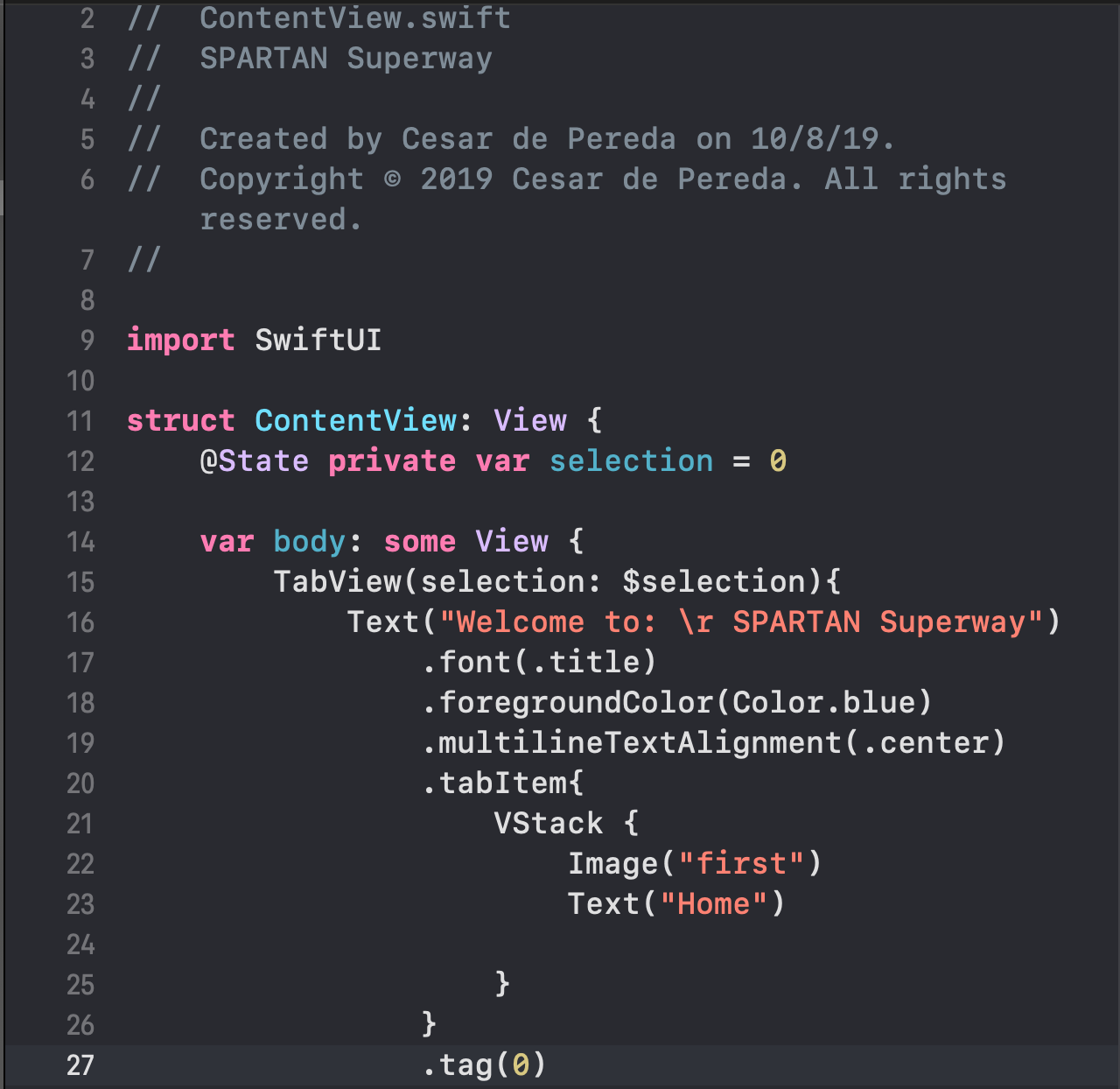 |
| Figure 2. Snippet of code so far. |
There are multiple parts being ordered at the moment, with a general idea of what needs to be included into the hardware for the controls. Figure 3 shows a Fritzing layout of the hardware, and a snippet of the motor code can be seen in Figure 4.
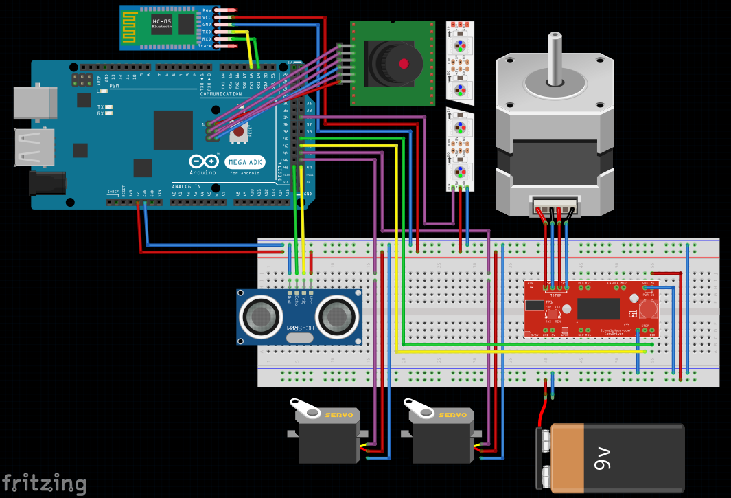 |
Figure 3. Fritzing layout of the Arduino and other hardware connected.
|
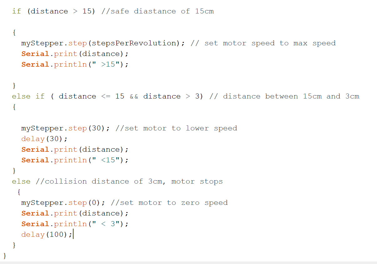 |
Figure 4. Code for motor.
|
Guideway Team
The guideway team has made considerable progress in the design of the track. Currently, there will be three main components: a base, stand and track. The base will be made of four pieces of plywood with a total area of 48 inches by 96 inches, as seen in Figure 5.
 |
Figure 5. Base of the guide way.
|
The track will also be made of plywood and connect to a stand with the help of an alignment tool. As seen in Figure 6a.
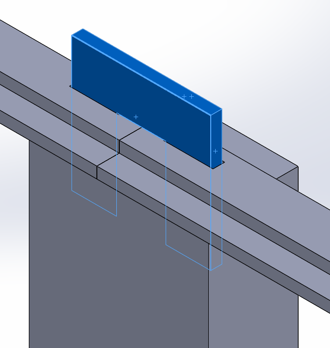 |
| Figure 6a. Track attached to stand with alignment tool. |
There will be multiple parts of the track, including curved and straight rails. The design for the y-junction needs to still be considered, as it will heavily affect the placement of the stands on the base. The idea for current manufacturing is to use a laser or water jet cutter to cut of the piece of wood. A rough assembly of the track has also been designed using CAD (Figure 6b).
 |
| Figure 6b. Assembly of half track. |
Bogie Team
The bogie team has also made progress by creating a snap-fit connection for the bogie and the pod (Figure 7). A swivel is also being considered to allow an easier turn around the bends of the track, as it has been done before in the Bill James Model (Figure 8).
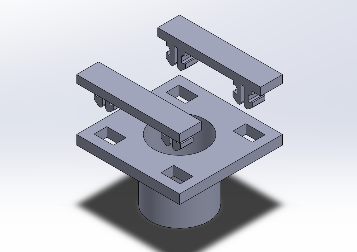 |
Figure 7. Snap fit connection.
|
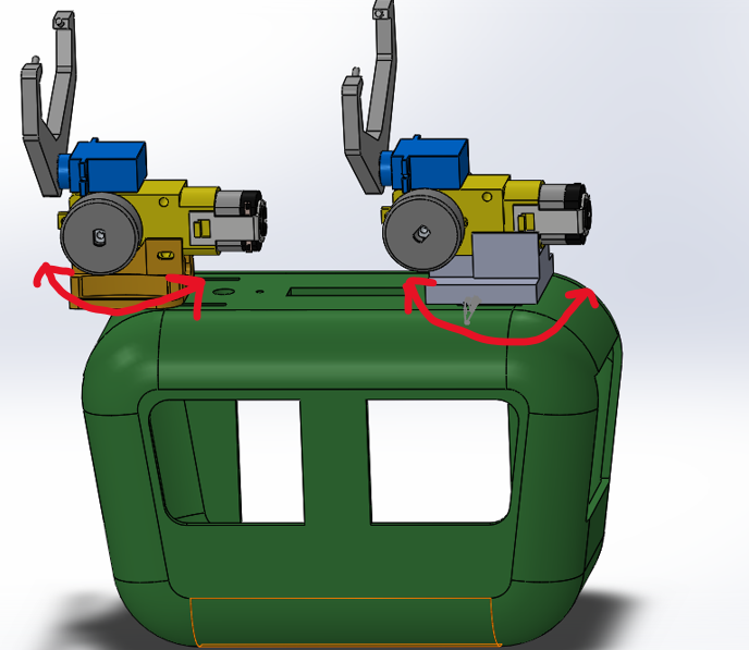 |
| Figure 8. Two swivels to allow easier turns. |
Team as a Whole
After relieving feed back from Professor Furman, Mr. Swenson and the rest of the students, there is much to be done in the coming weeks. Upcoming tasks for the Small Scale team include using CAD to redesign the bogie and pod. The 2nd Arduino and Swift drafts will also be created by the controls team. Finally, fabricating pieces of the track using any of the methods mentioned above will be completed, as well as assembling the track. Another note that needs to be mentioned is the y-junction. As there hasn't been too much work done on the bogie and it's connection to the track, the y-junction is a priority in the project. A mechanism for the switch will be created sometime soon within the next few weeks.
Plans for Next Week
Next week will continue with improving on the code, bogie and track. CAD will be heavily implemented and manufacturing costs will be considered. Mr. Swenson has currently set up an appointment with the Small Scale Team to demonstrate a laser cutter which will be coming in next week before Halloween.
Written By:
Justin Ghieuw
24 October, 2019
Comments
Post a Comment