SSST Blog 10/17/19
Progress for the week:
Controls Team
This week for the controls team, Asmaa continued working on combining the two main Arduino codes which we have so far. One of the codes was the one which implemented the ultrasonic sensor to get the motor to slow down if the ultrasonic sensor detected an object too close to it. This mimics what we want the bogies and pods to do once they are fully operational, it is essentially collision prevention system to where if a pod gets too close to another pod, the ultrasonic sensors will detect the proximity, and get the motor to slow down.
The other Arduino code which we have is for the BLE. Using a pre mad app to test if the BLE works, Asmaa wrote a code to enable the Arduino to turn an LED on and off depending on the input of the user on the app. If we typed 1, the LED would turn on and if we typed 0, the LED would turn off. Asmaa combined both of these codes into one, with the slight difference that once we have our own iOS app ready to connect to the BLE, we will be able to run the code from our app directly to the Arduino via the BLE. The following image shows a flow chart of the current code to turn the LED on and off with our phones via the pre made app.
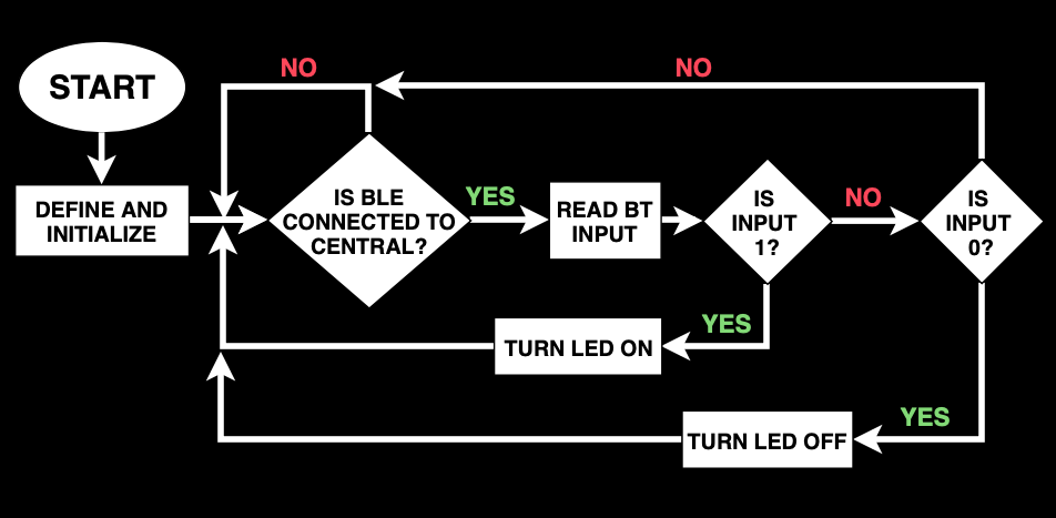
Figure 1: Flowchart of Arduino and BLE LED blinking code
The next image shown in figure 1 is the flow chart for the combined codes:
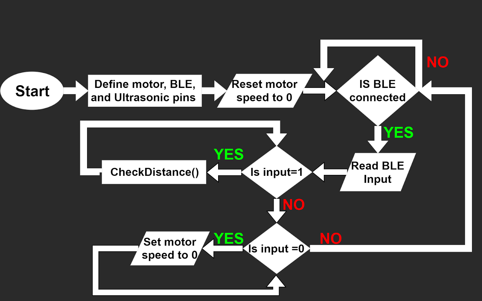
Figure 2: Combined Arduino codes to implement BLE, ultrasonic sensor and motor.
We also continued to make progress on the iOS app. The approach to creating the app was a bit different in the sense that for the current version of the app, I used Xcode's Storyboard mode which is a visual way of creating the UI of the app. It works by dragging and dropping different images, label or tools onto the View controllers (these are essentially the different "tabs" or layers of information on the app). The first version of the iOS app was done using Xcode's SwiftUI method which is pure code rather than visual UI. Both methods get the job done, they are just different approaches.
The three tabs still remain like on the first version, however, now the main tab (first tab from left) has a button which leads to a different tab with a brief intro to the small scale team. The second tab is where we are hoping to implement the BLE code so that we can connect directly to the Arduinos from the app. Lastly, the third tab is sort of vacant right now and we are thinking of different ideas as to what should go in this tab. For now it is just a tab with a View Map label. An image of the flow of the app can be seen in figure 3 below:

Figure 3: Flow of the apps storyboards for the different tabs and embedded tabs.
I was also able to download the iOS app on to my phone to continue testing. The app icon was updated and can be seen below in figure 4:

Figure 4: Updated app icon.
The name of the app can be disregarded for now, I will change it shortly. To get an idea as to how it looks and flows on the phone, a video can be seen below:
In terms of connecting our iOS app to the BLE, this has proven to be quite difficult and we have not been able to achieve it just yet. Lissette, Asmaa and I are all doing intensive research as to how to get this to work and we are piecing a lot of information together. We hope to be able to connect to the BLE from our app by the end of this semester. The overall look and layout of the app will continue to get updated in the following weeks as well. We are very happy with how everything is turning out so far for the app and the Arduino codes.
Guideway Team:
The guideway team has currently made progress on the track, going with the idea that the pieces of the railway will be built with plywood using a layered cake design. Currently the Makerspace was not able to contact the guideway team back regarding the use of the water jet cutter to trim out the pieces of the track from the plywood. However, CAD models have been developed and after careful consideration, Shane and Justin have determined to increase the width of the wood as well as the spacing between the rails for the bogie and pod. The inner and outer radius of the curved pieces will also be carefully considered and further modified to stay consistent with the bogie itself. The y-junction and stand have yet to be determined, but are the next big step sin moving forward with the project. The following images show some of the progress which has been made to the guideway.

Figure 5: Layered cake design of the track pieces

Figure 6: Overall track design with inner and outer loop

Figure 7: Curved parts of the track

Figure 8: Curved part of the track
This week the bogie and pod were designed and modeled on solid works. The pod was designed to be easy to assemble, print and make modifications. This was done by splitting the pod up into 5 different components. These components would then come together using a series of keys and press fits to stay in place. The connection between the bogie and the pod was designed such that it can swivel and disconnect from the bogie. The swiveling design was implemented so that the bogie could travel along the curves with ease. We also decided that to make maintenance of the bogie and pod easier that the connection should snap fit to the bogie. The design of the bogie still needs so be further developed, however a rough draft of the design was made. The following images depict the current status of the bogie and pod.

Figure 9: Pod design with swiveling connectors

Figure 10: Exploded view of pod along with pixie cam and ultrasonic sensor
 '
'Figure 11: Pod and bogie render exploded view

Figure 12: Pod and bogie render
Team As a Whole
The team met up pretty much every day of the week last week to continue working on the project along with finishing up the third presentation. Lots of progress was made on every aspect of the project and a solid presentation was put together. Yesterday our team presented our progress to the class and got feedback for the guideway and bogie designs. After the presentation, we solidified the next steps for the project which will happen in the next couple of weeks. We also began to plan out our final report.
Plans for next week
Due to the fact that next week is Thanksgiving break and we will not be meeting, work will continue to be done for the design of the bogie and a test print will take place within the next week to see how the pod and bogie turn out after we 3D print them. The guideway team will continue working on their design as well and might begin fabricating. The controls team will continue working on connecting the iOS app to the BLE as that is our top priority. We will regroup after spring break and continue on through this final stretch of the semester.
Written by:
Julio de Pereda Banda
November 21, 2019
Comments
Post a Comment